









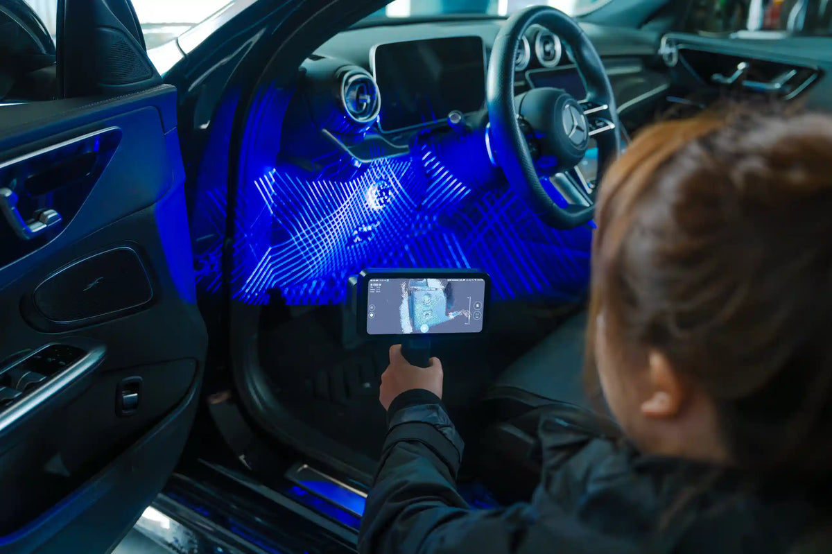
CNC machining often begins with a challenge: obtaining accurate digital geometry from existing parts, prototypes, or components that lack usable design files. Traditional measurement methods can require extensive manual inspection and CAD reconstruction before machining even starts. A 3D scanner for CNC helps streamline this process by capturing physical geometry as digital data, supporting faster scan-to-CAD workflows, more efficient CAM preparation, and improved manufacturing accuracy.
How 3D Scanning Fits into CNC Machining Workflows
Reducing Manual Measurement and CAD Reconstruction
Many CNC projects start with incomplete design information.Legacy components, worn replacement parts, and existing physical objects often lack current CAD files, forcing engineers to rely on calipers, gauges, and manual measurements.
This approach becomes increasingly difficult when parts contain freeform surfaces, organic shapes, internal transitions, or complex mechanical features. Multiple measurements must be interpreted and recreated manually, introducing opportunities for error and extending engineering timelines.
3D scanning addresses this challenge by capturing the entire geometry of a part as a point cloud or mesh dataset. Instead of measuring selected dimensions individually, engineers obtain a comprehensive digital representation that can be used for CAD reconstruction. This reduces the effort required to recreate complex surfaces and allows design teams to focus on engineering decisions rather than data collection.
From Scan Data to CAD and CAM
3D scanning for CNC is the process of converting physical parts into digital models that can be used for CAD reconstruction, CAM preparation, and machining.
A typical workflow follows these steps:
- Scan the physical part
- Generate point cloud or mesh data
- Create a CAD model
- Prepare machining strategies in CAM software
- Generate toolpaths
- Manufacture the part using CNC equipment
The scanned data serves as a reference for creating parametric CAD models suitable for engineering modification and manufacturing. Once the CAD model is complete, CAM software can generate machining operations and toolpaths based on the desired production process.
This scan-to-CAD-to-CAM workflow is particularly valuable when working with replacement parts, custom components, or products that must be modified before production.
Verifying Finished Parts Through Digital Comparison
The value of scanning does not end once machining begins. Many manufacturers also use 3D scanning for dimensional inspection and quality verification.
After machining, the finished component can be scanned and compared against the CAD model. Digital comparison tools help identify deviations between the manufactured part and the design intent, supporting tolerance verification and process validation.
This approach can reveal dimensional issues that may be difficult to detect through traditional spot measurements alone. For parts with complex surfaces or tight tolerances, digital comparison provides a more complete view of geometric accuracy and helps manufacturers identify corrective actions before assembly or delivery.
Common CNC Applications for 3D Scanning
Reverse Engineering Legacy and Replacement Components
Reverse engineering remains one of the most common uses of 3D scanning in CNC manufacturing.
Many industries continue to operate equipment that has been in service for years or decades. When replacement components fail, original CAD files may no longer exist. Recreating these parts manually can require significant engineering effort.
By scanning the existing component, engineers can generate accurate digital references for CAD reconstruction. The resulting CAD model can then be modified, optimized, or directly prepared for manufacturing.
This process is especially useful for replacement parts that must match existing assemblies while maintaining functional compatibility.
Rapid Prototyping and Product Development
Product development teams frequently work with physical prototypes that evolve through multiple design iterations.
When a prototype must be modified, measured, or prepared for production, scanning provides a fast way to capture current geometry without rebuilding the model from scratch. Engineers can compare prototype versions, evaluate design changes, and incorporate modifications into updated CAD files.
The ability to move quickly between physical objects and digital models supports rapid prototyping workflows and helps reduce delays between design reviews and manufacturing preparation.
For organizations developing custom products or low-volume components, scanning can accelerate the transition from concept validation to CNC machining.
Fixture, Tooling, and Custom Manufacturing
Fixtures, jigs, molds, and custom tooling often require precise alignment with existing components.
In these applications, scanning enables engineers to capture the geometry of mating surfaces and surrounding assemblies before designing supporting fixtures. The resulting digital data helps ensure proper fit and reduces the risk of costly rework.
Custom manufacturing environments also benefit from scanning when parts vary from project to project. Rather than building designs around estimated dimensions, engineers can work from actual geometry captured directly from the physical object.
This improves design confidence and supports more predictable CNC workflows.
Key Considerations for CNC 3D Scanning
Part Complexity and Accuracy Requirements
Not every CNC application requires the same level of geometric detail.
Simple prismatic parts may be measured effectively using conventional inspection methods, while freeform surfaces, cast components, and intricate mechanical assemblies often benefit significantly from 3D scanning.
The required accuracy should always be determined by the part's function, manufacturing tolerances, and downstream machining requirements. While 3D scanning is highly effective for capturing accessible external geometry, critical features such as internal bores, threads, sealing surfaces, and other precision interfaces may still require verification using conventional measuring tools or CMM inspection. Selecting an appropriate scanning solution begins with understanding how the data will be used during CAD reconstruction, machining, and inspection.
Reflective Surfaces and Difficult Materials
Highly reflective, polished, dark, or translucent surfaces can create challenges during data capture.
These materials may scatter or absorb projected light, resulting in incomplete scan data. Depending on the part and scanning environment, manufacturers may use surface preparation methods to improve data quality and reduce missing regions within the mesh.
Proper scanning practices become particularly important when reverse engineering components that contain fine mechanical details or critical mating features.
CAD and CAM Software Compatibility
A successful scan-to-CNC workflow depends on more than data capture alone.
Engineering teams should ensure that scan outputs can integrate smoothly with their existing CAD and CAM software. Common workflows involve transferring mesh data into reverse engineering or CAD reconstruction tools before generating manufacturing-ready models.
Efficient interoperability helps reduce file conversion issues, shortens engineering cycles, and supports a more streamlined path from scanning to toolpath generation.
EINSTAR Solutions for Scan-to-CNC Workflows
A successful CNC workflow depends on more than capturing scan data. The information must move efficiently from physical geometry to CAD reconstruction and ultimately into CAM preparation.
For reverse engineering and CNC manufacturing projects, EinScan Rigil Lite can be used to capture mesh data from existing parts, prototypes, or replacement components. Its Laser HD mode supports resolution from 0.05 mm, while 17+17 crossed blue laser lines help capture detailed geometry on mechanical components. The resulting scan data can then be incorporated into a scan-to-CAD workflow, reducing the amount of manual measurement required during model creation.

For the reconstruction stage, EXModel provides tools for converting mesh data into editable CAD geometry. Once a CAD model has been generated, it can be transferred into compatible CAD and CAM software for machining preparation and toolpath generation.
Combining 3D scanning with CAD reconstruction software helps create a more efficient path from physical parts to CNC-ready manufacturing data.
Conclusion
A 3D scanner for CNC helps bridge the gap between physical components and digital manufacturing by supporting scan-to-CAD, CAM preparation, dimensional verification, and reverse engineering workflows. For CNC machining teams, this approach reduces manual reconstruction effort and improves process efficiency. Solutions such as the EinScan Rigil Lite fit naturally into modern scan-to-CNC workflows where accurate digital geometry is essential for manufacturing success.
FAQ
1. What file formats are commonly used between 3D scanning, CAD, and CAM software?
Common scan formats include STL, OBJ, and PLY mesh files. CAD software typically works with formats such as STEP or IGES, while CAM software uses CAD geometry to generate machining toolpaths.
2. Can handheld 3D scanners capture complex mechanical parts with fine details?
Yes. Modern handheld 3D scanners can capture intricate geometries, curved surfaces, and mechanical features that are difficult to document through manual measurement alone, making them useful for reverse engineering and product development.
3. How much time can a scan-to-CNC workflow save compared to manual measurement methods?
Time savings vary by project complexity. For parts with complex surfaces or missing CAD files, scanning can significantly reduce measurement and CAD reconstruction effort by capturing large amounts of geometric data in a single workflow.
Share:
3D Parts Scanner: Mechanical Reverse Engineering Guide